Showing posts with label
How rectifier AC current as DC.
Show all posts
Showing posts with label
How rectifier AC current as DC.
Show all posts
Most popular full-wave rectifier design exists, and it is built around a four-diode bridge configuration. For obvious reasons, this design is called a full-wave bridge.
 Current directions for the full-wave bridge rectifier circuit are as shown in Image for positive half-cycle and negative half-cycles of the AC source waveform. Note that regardless of the polarity of the input, the current flows in the same direction through the load. That is, the negative half-cycle of source is a positive half-cycle at the load. The current flow is through two diodes in series for both polarities. Thus, two diode drops of the source voltage are lost (0.7 2=1.4 V for Si) in the diodes. This is a disadvantage compared with a full-wave center-tap design. This disadvantage is only a problem in very low voltage power supplies.
Remembering the proper layout of diodes in a full-wave bridge rectifier circuit can often be frustrating to the new student of electronics. I’ve found that an alternative representation of this circuit is easier both to remember and to comprehend. It’s the exact same circuit, except all diodes are drawn in a horizontal attitude, all “pointing” the same direction.
If we need to rectify AC power to obtain the full use of both half-cycles of the sine wave, a different rectifier circuit configuration must be used. Such a circuit is called a full-wave rectifier. One kind of full-wave rectifier, called the center-tap design, uses a transformer with a center-tapped secondary winding and two diodes.
This circuit’s operation is easily understood one half-cycle at a time. Consider the first half cycle, when the source voltage polarity is positive (+) on top and negative (-) on bottom. At this time, only the top diode is conducting; the bottom diode is blocking current, and the load “sees” the first half of the sine wave, positive on top and negative on bottom. Only the top half of the transformer’s secondary winding carries current during this half-cycle.
During the next half-cycle, the AC polarity reverses. Now, the other diode and the other half of the transformer’s secondary winding carry current while the portions of the circuit formerly
carrying current during the last half-cycle sit idle. The load still “sees” half of a sine wave, of the same polarity as before: positive on top and negative on bottom.
One disadvantage of this full-wave rectifier design is the necessity of a transformer with a center-tapped secondary winding. If the circuit in question is one of high power, the size and
expense of a suitable transformer is significant. Consequently, the center-tap rectifier design is only seen in low-power applications.
The full-wave center-tapped rectifier polarity at the load may be reversed by changing the direction of the diodes. Furthermore, the reversed diodes can be paralleled with an existing positive-output rectifier. The result is dual-polarity full-wave center-tapped rectifier in below diagram. Note that the connectivity of the diodes themselves is the same configuration as a bridge.
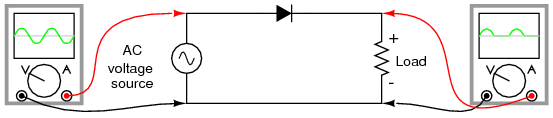
Rectification is the conversion of alternating current (AC) to direct current (DC). This involves a device that only allows one-way flow of electrons. As we have seen, this is exactly what a semiconductor diode does. The simplest kind of rectifier circuit is the half-wave rectifier. It only allows one half of an AC waveform to pass through to the load.
 For most power applications, half-wave rectification is insufficient for the task. The harmonic content of the rectifier’s output waveform is very large and consequently difficult to filter. Furthermore, the AC power source only supplies power to the load one half every full cycle, meaning that half of its capacity is unused. Half-wave rectification is, however, a very simple way to reduce power to a resistive load. Some two-position lamp dimmer switches apply full AC power to the lamp filament for “full” brightness and then half-wave rectify it for a lesser light output.
 In the “Dim” switch position, the incandescent lamp receives approximately one-half the power it would normally receive operating on full-wave AC. Because the half-wave rectified power pulses far more rapidly than the filament has time to heat up and cool down, the lamp does not blink. Instead, its filament merely operates at a lesser temperature than normal, providing less light output. This principle of “pulsing” power rapidly to a slow responding load device to control the electrical power sent to it is common in the world of industrial electronics. Since the controlling device (the diode, in this case) is either fully conducting or fully nonconducting at any given time, it dissipates little heat energy while controlling load power, making this method of power control very energy-efficient. This circuit is perhaps the crudest possible method of pulsing power to a load, but it suffices as a proof-of concept application.